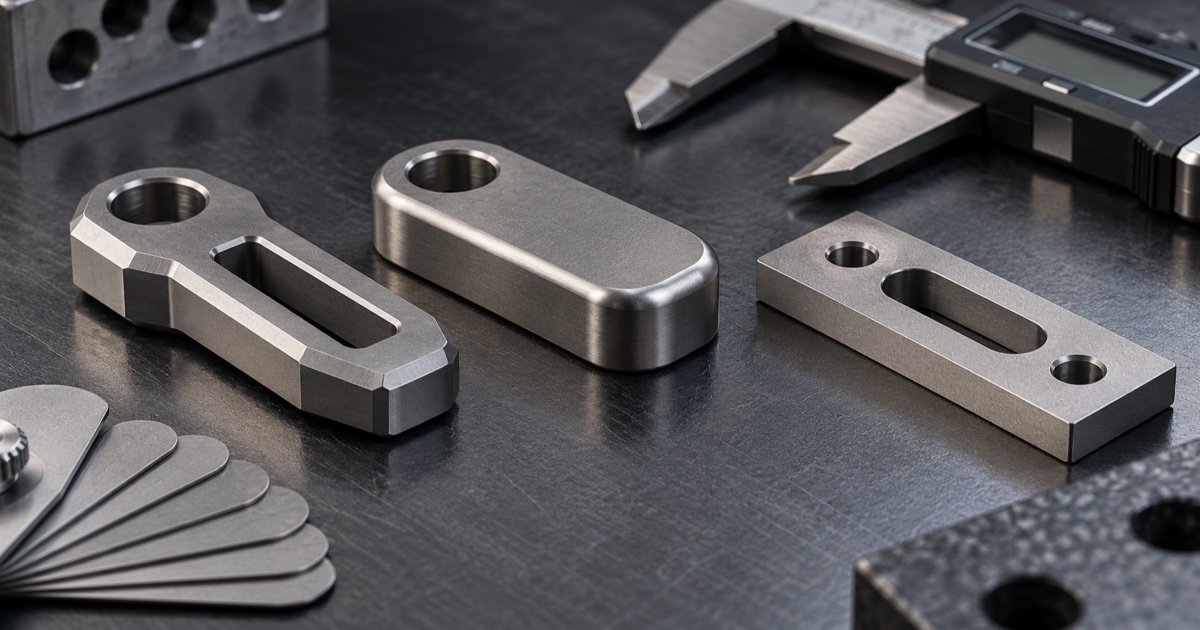
“Deburr all edges” may be enough for a rough prototype, but it is rarely a complete production requirement for a titanium EDC product. An edge can affect grip comfort, pocket wear, assembly clearance, coating or anodizing appearance, cleaning, logo placement, and the way inspectors judge a finished part.
A useful drawing separates functional edges from cosmetic and safety-related edges, then states whether each one needs a controlled chamfer, radius, intentionally sharp condition, or a general edge break. This guide explains how product teams can make those choices without applying one arbitrary value to the entire design.
Edge Break, Chamfer, Radius, and Deburring Are Not the Same
Deburring removes unintended burrs left by machining, drilling, cutting, or handling. An edge break intentionally removes the sharp corner, but the resulting form may not be tightly controlled unless the drawing says otherwise. A chamfer creates a flat angled surface. A radius creates a curved transition.
These terms should not be used interchangeably when geometry matters. A broad cosmetic chamfer, a small handling edge break, and a controlled sealing or assembly radius serve different purposes. If the distinction affects function or appearance, show it on the drawing and identify the inspection method.
Edge Treatment Comparison
| Edge condition | Typical purpose | What needs definition | Common risk if vague |
|---|---|---|---|
| Deburred edge | Remove unintended machining burrs | Permitted residual condition and inspection method | Parts pass visually but still feel inconsistent |
| General edge break | Reduce sharpness on noncritical exposed edges | Size range, affected edges, and exclusions | Too much material is removed from nearby features |
| Chamfer | Create a visible bevel, lead-in, or assembly feature | Width or leg size, angle, continuity, and endpoints | Appearance changes around corners or intersections |
| Radius | Create a smoother transition for touch or geometry | Radius value, blend, continuity, and measurement method | Hand finishing produces an uneven profile |
| Controlled sharp edge | Preserve a working or mating feature | Maximum edge break, burr prohibition, and protection requirements | Normal deburring destroys the intended feature |
| Cosmetic transition | Control a visible highlight or finish boundary | Reference sample, viewing condition, and geometry | Nominally conforming parts look different under light |
Classify Edges by Function
Begin by marking every edge that the user touches, that contacts clothing or adjacent gear, that guides assembly, that forms part of a mechanism, or that affects a working feature. The same product may need a comfortable rounded grip edge, a controlled chamfer at a threaded opening, and a protected working corner elsewhere.
This is why a blanket note can create trouble. A technician may correctly remove burrs yet change an edge that controls fit, visual alignment, or tool function. Connect edge decisions with the approach in choosing tolerances for titanium EDC products so the tightest control is reserved for characteristics that matter.
Design for Hands, Pockets, and Adjacent Gear
EDC products are handled frequently and often share a pocket with fabric, phones, organizers, or other tools. Review external corners, slot edges, attachment holes, pocket clips, grip cutouts, and fastener recesses in the complete assembly. A single sharp intersection can dominate the user experience even when the rest of the body is smooth.
Test representative hand positions rather than inspecting the product only on a bench. If the intended market includes cold-weather or work-glove use, use the evaluation principles in designing compact metal EDC tools for gloves. The edge that helps a bare finger locate a control may behave differently through thick fabric.
Protect Functional Interfaces
Lead-in chamfers can help components start into bores, threaded openings, caps, or mating features, but their size changes the remaining contact length and local geometry. Radii may reduce an abrupt transition while also affecting clearance. Define the functional stack before adding edge treatments as a styling detail.
For threaded titanium parts, the entrance condition, thread start, cleaning, and assembly method belong in the same review. The article on titanium thread galling and prevention explains why material pairing, surface condition, fit, contamination, and assembly practice must be considered together.
Account for Finishing and Appearance
A chamfer can create a deliberate highlight that makes a compact tool look more defined. A large radius creates a softer transition and may display brushed, blasted, stonewashed, polished, or anodized finishes differently from a flat face. Edge geometry can also influence how contact marks and color variation are perceived.
Freeze important edge geometry before approving cosmetic samples. Then evaluate it with the chosen process using the titanium surface finish guide. If hand blending is allowed, specify where and how consistency will be judged rather than relying on the phrase “smooth finish.”
Avoid Uncontrolled Hand Finishing
Manual deburring and blending can be useful, especially around complex intersections, but an undefined manual step can create variation in width, symmetry, profile, or texture. It may also round a corner that was intended to remain crisp.
During DFM review, ask which edges are produced directly by the machining path, which require a separate tool, and which require hand work. The DFM process for EDC products can help teams identify inaccessible edges and cosmetic transitions before the first sample.
Put the Requirement in the Right Place
Use a general drawing note for truly common noncritical edges. Apply local callouts where a feature needs a different size, angle, radius, or maximum break. Add a marked image or cosmetic map when appearance zones are easier to communicate visually, but do not let an image replace measurable geometry.
A controlled requirement can include:
- the edges covered by the note;
- the permitted size or range;
- features excluded from the general rule;
- whether a burr is permitted in any direction;
- the intended inspection method;
- the relationship to the approved finish sample;
- any post-finishing condition that must be checked again.
Inspect Edges With More Than One Method
Visual inspection under consistent lighting can reveal irregular highlights, incomplete deburring, or damaged finish. Touch evaluation can reveal discomfort or snagging, but it is subjective and should be performed with a defined method. Dimensional tools, radius gauges, optical methods, or profile comparison may be appropriate when geometry is critical.
Check several locations and part orientations. A chamfer can be correct on a straight section but inconsistent near a corner, slot, or intersecting hole. Record the drawing revision, finish condition, sample identity, and instrument or comparison method.
Prototype the Edge, Not Just the Overall Shape
Early prototypes often focus on overall dimensions and mechanism function. Edge treatments should still be reviewed before production intent is frozen because they affect touch, assembly, finish, and visual proportion. If the prototype uses a temporary process, label which edge results are representative and which are not.
Add edge checks to the titanium EDC prototype testing checklist. For a pry tool, inspect the relationship between working edges and handling edges using the titanium pry bar product category as a reference for different architectures.
Common Specification Mistakes
- Using “break all sharp edges” without a size range or exclusions.
- Applying the same edge treatment to grip, assembly, cosmetic, and working features.
- Adding a large chamfer after tolerances and fit have already been approved.
- Ignoring interior slot, hole, and clip-contact edges.
- Expecting finishing to hide inconsistent geometry.
- Approving one attractive sample without defining repeatable inspection.
- Failing to recheck edges after blasting, stonewashing, polishing, or other secondary processes.
FAQ
Is “deburr all edges” enough on a production drawing?
It may be adequate for noncritical hidden features, but exposed, functional, cosmetic, or intentionally sharp edges usually need clearer local or general requirements.
Should every exposed titanium edge have a radius?
No. Chamfers, radii, and smaller edge breaks create different feel, appearance, access, and manufacturing requirements. Select them by function.
Can a finish process replace mechanical deburring?
Do not assume it can. The process sequence and expected edge condition should be reviewed and validated for the specific geometry and finish.
How should edge comfort be approved?
Combine defined geometry and visual criteria with a repeatable handling check using representative users or use conditions. A vague “feels good” comment is difficult to reproduce.
Preparing a Titanium EDC Drawing?
Explore the Product Development hub for related engineering decisions. Brands can review Alloywright’s product development capabilities or submit a drawing or sample for manufacturability review.